
Obwody logiczne
 35 min.,
  2/3
2/3 Które zaklęcie może włączyć właściwy wskaźnik świetlny w przeciążonej windzie, przygotować pomarańczowy napój gazowany poprzez naciśnięcie przycisku na automacie, wyłączyć światła w korytarzu domu po kilku minutach, lub przesunąć postać na ekranie komputera? Te i wiele innych rzeczywistych czynności jest obsługiwanych przez układy logiczne, które omówimy bardziej szczegółowo w poniższej serii problemów.
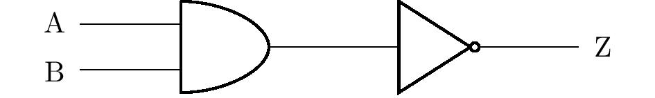
Obwody logiczne składają się z tak zwanych bramek logicznych, które implementują operacje logiczne. W ćwiczeniach będziemy pracować tylko z trzema podstawowymi bramkami logicznymi, a mianowicie NOT (negacja), AND (koniunkcja) i OR (dysjunkcja). Rysunek przedstawia ich odpowiednie symbole (zgodnie z amerykańskim standardem ANSI/MIL) w obwodach logicznych. Są one zorientowane tak, że kierunek wejścia jest z lewej strony. Wejścia są rozumiane jako instrukcje, podczas gdy wyjścia są instrukcjami złożonymi.
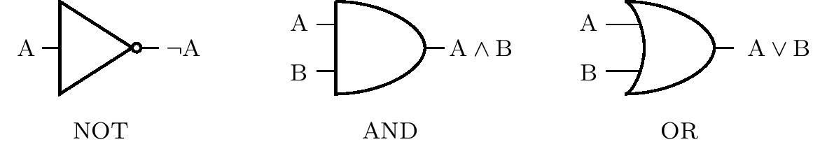
Wartości prawdy są implementowane w obwodach logicznych za pomocą napięcia. Niskie napięcie wskazuje wartość prawdy 0, podczas gdy wysoki poziom napięcia wskazuje wartość 1. Na przykład, jeśli bramka AND ma niski poziom napięcia na wejściu A i wysoki poziom napięcia na wejściu B, wyjściem jest poziom niskiego napięcia. Konkretne wartości poziomów różnią się w zależności od konkretnego zastosowania obwodu. Niski poziom około 0 V i wysoki poziom około 5 V są powszechne.
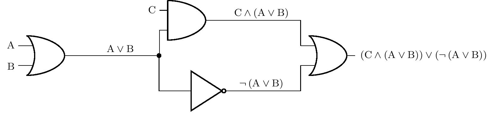
Na kolejnym rysunku widzimy reprezentację bardziej złożonego obwodu logicznego. Dla przejrzystości, rysunek pokazuje również sekwencyjne łączenie instrukcji, które odpowiadają wejściom lub wyjściom poszczególnych bramek. Czarna kropka wskazuje węzeł, w którym obwód logiczny rozgałęzia się. W ten sposób wyjście jednej bramki może być doprowadzone do wielu wejść w tym samym czasie.
W poniższych ćwiczeniach przełączniki lub przyciski można umieścić przed wejściami, a żarówki mogą być umieszczone za wyjściami obwodu logicznego. Przyjmijmy, że wartość logiczna na wejściu jest równa 1 wtedy i tylko wtedy, gdy przełącznik jest włączony lub przycisk jest naciśnięty. Podobnie, żarówka zapala się wtedy i tylko wtedy, gdy na odpowiednim wyjściu jest wartość logiczna 1.
Zadanie 1. W obwodzie przedstawionym na poprzednim rysunku przed wejściami A, B i C znajdują się przełączniki, a do wyjścia podłączona jest żarówka. Jeśli przełącznik C nie jest włączony, w jakiej pozycji muszą znajdować się przełączniki A i B, aby żarówka się zaświeciła?
Rozwiązanie. Niech \(p(\mathrm{X})\) oznacza wartość prawdziwą stwierdzenia \(\mathrm{X}\). Z przypisania wiemy, że \(p(\mathrm{C})=0\) i pytamy o wartości \(p(\mathrm{A})\) i \(p(\mathrm{B})\) takich, że \(p\left[ \left(\mathrm{C}\wedge \left(\mathrm{A}\vee\mathrm{B}\right)\right)\vee \left( \neg\left(\mathrm{A}\vee\mathrm{B}\right)\right) \right]=1\). Rozwiążemy zadanie poprzez rozumowanie.
Jeśli \(p(\mathrm{C})=0\) zachodzi, to koniecznie \(p(\mathrm{C}\wedge \left(\mathrm{A}\vee\mathrm{B}\right))=0\).Dlatego stwierdzenie \(\neg ( \mathrm{A}\vee \mathrm{B})\) musi być prawdziwe, a zatem \(p(\mathrm{A}\vee \mathrm{B})=0\). Jest to jednak możliwe wtedy i tylko wtedy, gdy stwierdzenia \(\mathrm{A}\) i \(\mathrm{B}\) są fałszywe. Dlatego oba przełączniki muszą pozostać zamknięte.
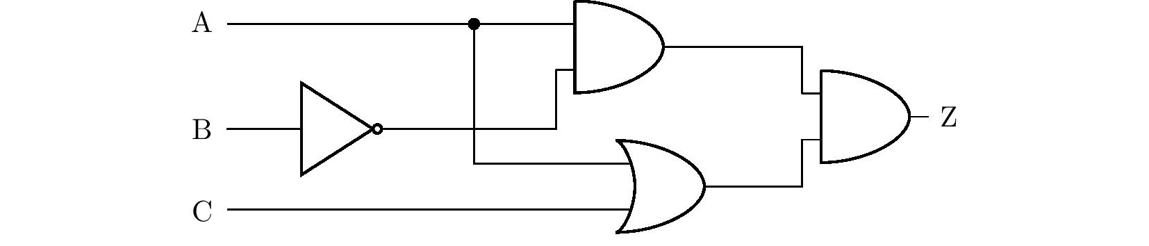
Zadanie 2. Obwód logiczny pokazany na poniższym rysunku ma przełączniki na wejściach A, B i C oraz żarówkę na wyjściu Z. Które przełączniki muszą być włączone, aby żarówka się zaświeciła? Znajdź wszystkie rozwiązania zadania. Jeśli przewody przecinają się na schemacie bez pokazania węzła, zakłada się, że nie ma rzeczywistego kontaktu między przewodami.
Rozwiązanie. Rozwiążemy ten problem za pomocą tablicy prawdy. Z diagramu w zadaniu najpierw wyprowadzamy twierdzenie składające się ze stwierdzeń \(\mathrm{A}\), \(\mathrm{B}\) i \(\mathrm{C}\), które będą równoważne stwierdzeniu \(\mathrm{Z}\), patrz rysunek.
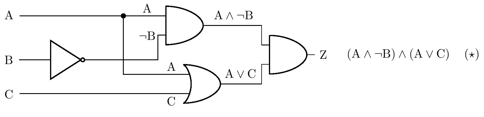
Dla instrukcji złożonej \(\left( \star \right)\) tworzymy teraz tabelę prawdy:
| \(\mathrm{A}\) | \(\mathrm{B}\) | \(\mathrm{C}\) | \(\mathrm{A}\wedge\neg\mathrm{B}\) | \(\mathrm{A}\vee\mathrm{C}\) | \(\left( \mathrm{A}\wedge\neg\mathrm{B}\right) \wedge \left( \mathrm{A}\vee\mathrm{C} \right)\) |
|---|---|---|---|---|---|
| \(1\) | \(1\) | \(1\) | \(\quad0\) | \(\quad1\) | \(\qquad\qquad0\) |
| \(1\) | \(1\) | \(0\) | \(\quad0\) | \(\quad1\) | \(\qquad\qquad0\) |
| \(1\) | \(0\) | \(1\) | \(\quad1\) | \(\quad1\) | \(\qquad\qquad1\) |
| \(1\) | \(0\) | \(0\) | \(\quad1\) | \(\quad1\) | \(\qquad\qquad1\) |
| \(0\) | \(1\) | \(1\) | \(\quad0\) | \(\quad1\) | \(\qquad\qquad0\) |
| \(0\) | \(1\) | \(0\) | \(\quad0\) | \(\quad0\) | \(\qquad\qquad0\) |
| \(0\) | \(0\) | \(1\) | \(\quad0\) | \(\quad1\) | \(\qquad\qquad0\) |
| \(0\) | \(0\) | \(0\) | \(\quad0\) | \(\quad0\) | \(\qquad\qquad0\) |
Tabela pokazuje, że żarówka świeci, jeśli przełącznik A jest zamknięty, a przełącznik B nie jest zamknięty w tym samym czasie. Pozycja przełącznika C nie ma znaczenia. Problem ten można również rozwiązać za pomocą równoważnych modyfikacji stwierdzenia \(\left(\star \right)\). Najpierw używamy prawa rozdzielności, a następnie tak zwanego prawa idempotentnego \(\mathrm{A}\wedge \mathrm{A}\Leftrightarrow \mathrm{A}\):
\[ \begin{alignat*}{3} &&&\left( \mathrm{A}\wedge\neg\mathrm{B}\right) \wedge \left( \mathrm{A}\vee\mathrm{C} \right) &&\quad\Leftrightarrow\\ &\Leftrightarrow\quad &&\left( \mathrm{A}\wedge\neg\mathrm{B}\wedge\mathrm{A}\right) \vee \left( \mathrm{A}\wedge\neg\mathrm{B}\wedge\mathrm{C}\right) &&\quad\Leftrightarrow\\ &\Leftrightarrow\quad &&\left( \mathrm{A}\wedge\neg\mathrm{B}\right) \vee \left( \mathrm{A}\wedge\neg\mathrm{B}\wedge\mathrm{C}\right). && \tag{$\star\star$} \end{alignat*} \]
Jednak złożone stwierdzenie $( ) $ jest prawdziwe wtedy i tylko wtedy, gdy koniunkcja \(\mathrm{A}\wedge\neg\mathrm{B}\) jest prawdziwe wtedy i tylko wtedy, gdy koniunkcja \(\mathrm{A}\wedge\neg\mathrm{B}\) jest prawdziwa, tzn. jeśli \(\mathrm{A}\) jest prawdziwym stwierdzeniem, a \(\mathrm{B}\) jest fałszywym stwierdzeniem. Nasuwa to ten sam wniosek dotyczący pozycji przełączników, który wyciągnęliśmy za pomocą tabeli.
Zadanie 3. Zaprojektuj obwód logiczny, który w przypadku awarii jednej z dwóch pomp wodnych (lub obu) zapali lampkę ostrzegawczą na wyjściu obwodu. Dopóki pompa działa, wysyła sygnał odpowiadający logicznej jedynce do jednego z dwóch wejść obwodu.
Rozwiązanie. Oznaczmy \(\mathrm{A}\) i \(\mathrm{B}\) jako stwierdzenia reprezentujące stan pierwszej i drugiej pompy. Szukamy stwierdzenia \(\mathrm{Z}\) złożonego z \(\mathrm{A}\) i \(\mathrm{B}\), którego tabelę prawdy znamy z \(\mathrm{A}\) i \(\mathrm{B}\), którego tablicę prawdy znamy:
| \(\mathrm{A}\) | \(\mathrm{B}\) | \(\mathrm{Z}\) |
|---|---|---|
| \(1\) | \(1\) | \(0\) |
| \(1\) | \(0\) | \(1\) |
| \(0\) | \(1\) | \(1\) |
| \(0\) | \(0\) | \(1\) |
Tabela pokazuje, że równoważnym stwierdzeniem jest \(\neg\left( \mathrm{A} \wedge \mathrm{B}\right)\), co odpowiada schematowi obwodu wynikowego na rysunku:
Zadanie ma więcej rozwiązań. Na przykład, korzystając z prawa de Morgana, z poprzedniego wyniku otrzymujemy równoważne stwierdzenie \(\neg\mathrm{A}\vee\neg\mathrm{B}\). Stwierdzenie to można przedstawić za pomocą innego, ale równie poprawnego schematu obwodu.
Zadanie 4. Zmodyfikuj urządzenie ostrzegawcze z poprzedniego ćwiczenia. Czerwone i zielone światła zostaną teraz podłączone do dwóch wyjść. Jeśli obie pompy działają, świeci się zielona kontrolka, a czerwona kontrolka jest wyłączona. Jeśli jedna z pomp ulegnie awarii, zapali się również czerwona lampka, a jeśli obie pompy ulegną awarii, świeci się tylko czerwona dioda. Zaprojektuj odpowiedni obwód logiczny.
Rozwiązanie. Podobnie jak w poprzednim zadaniu, oznaczmy \(\mathrm{A}\) i \(\mathrm{B}\) przez \(\mathrm{A}\). i \(\mathrm{B}\) stwierdzenia reprezentujące stan pierwszej i drugiej pompy. W ten sposób otrzymujemy tabelę prawdy wartości nieznanych stwierdzeń złożonych \(\mathrm{R}\) (światło czerwone) i \(\mathrm{G}\) (światło zielone):
| \(\mathrm{A}\) | \(\mathrm{B}\) | \(\mathrm{R}\) | \(\mathrm{G}\) |
|---|---|---|---|
| \(1\) | \(1\) | \(0\) | \(1\) |
| \(1\) | \(0\) | \(1\) | \(1\) |
| \(0\) | \(1\) | \(1\) | \(1\) |
| \(0\) | \(0\) | \(1\) | \(0\) |
Widzimy, że kolumna dla wyrażenia \(\mathrm{R}\) jest identyczna z kolumną dla wyrażenia \(\mathrm{Z}\) z poprzedniego zadania (a zatem możemy przyjąć jego rozwiązanie), a kolumna dla stwierdzenia \(\mathrm{G}\) odpowiada dysjunkcji \(\mathrm{A}\vee \mathrm{B}\). Używając węzłów i rozgałęziając obwód, możemy narysować schemat odpowiedniego obwodu logicznego:
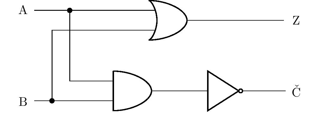
Podobnie jak poprzednie zadanie, to również ma wiele rozwiązań, których poprawność zawsze można zweryfikować za pomocą tabeli prawdy. Omówimy jednak jedno z rozwiązań bardziej szczegółowo.
Uczniowie mogą pomyśleć, że zamiast bramki OR, przewody można połączyć prostym węzłem, jak pokazano na rysunku: 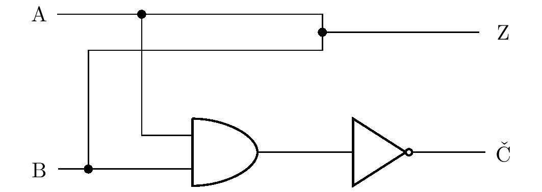
Jeśli na \(\mathrm{A}\) lub \(\mathrm{B}\) (lub na obu) znajduje się wartość \(1\), czy ta wartość może swobodnie przepływać do wyjścia \(\mathrm{G}\,\)? W rzeczywistości tak nie jest. W pierwszym akapicie, zauważyliśmy, że wartość prawdy \(1\) jest realizowana przez wysoki poziom napięcia, a wartość \(0\) przez jego niski poziom. Na przykład, jeśli na wejściu \(\mathrm{A}\) występuje wysokie napięcie, a na wejściu \(\mathrm{B}\) niskie napięcie. i niskie napięcie na wejściu \(\mathrm{B}\), w obwodzie wystąpi zwarcie, ponieważ punkty o różnych napięciach są połączone przewodem. Dlatego też, ogólnie rzecz biorąc, nie możemy łączyć wyjść różnych bramek za pomocą węzłów w obwodach logicznych.
Zadanie 5. Zaprojektuj obwód logiczny z dwoma wejściami i jednym wyjściem, który wykonuje równoważność logiczną. Rozwiązanie.* Aby skonstruować obwód, musimy znaleźć równoważne \(\mathrm{A}\Leftrightarrow\mathrm{B}\) z tą samą tabelą prawdy, która zawiera tylko spójniki lub negacje.
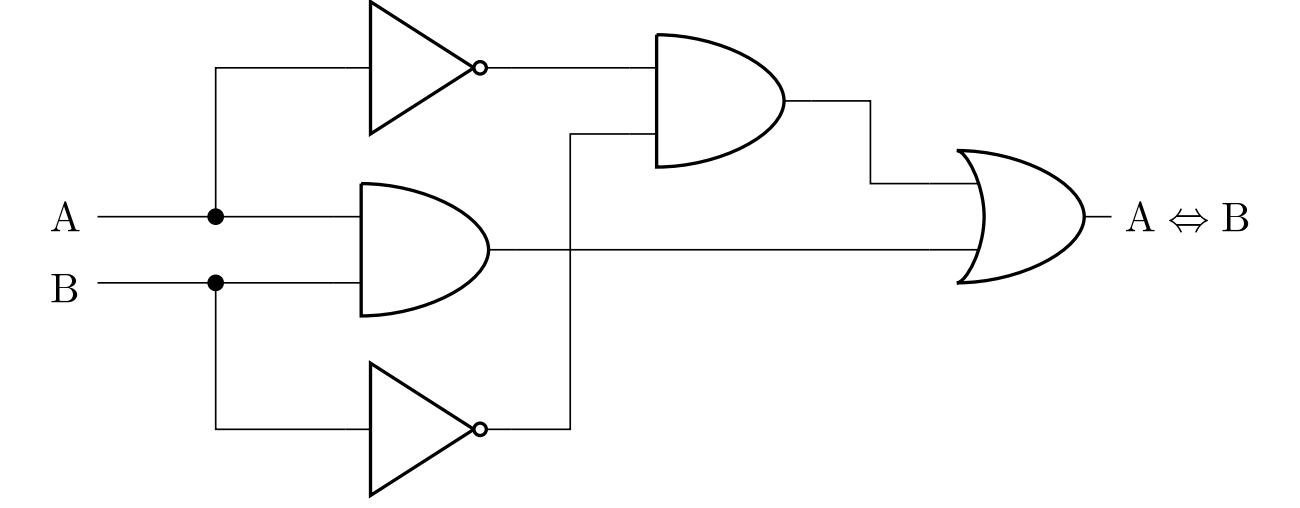
Rozwiązanie. Z definicji równoważności wynika, że jest ona prawdziwa wtedy i tylko wtedy, gdy stwierdzenia \(\mathrm{A}\) i \(\mathrm{B}\) są prawdziwe lub fałszywe. Czyli jest prawdziwe wtedy i tylko wtedy, gdy koniunkcja \(\mathrm{A}\wedge\mathrm{B}\) jest prawdziwa lub koniunkcja \(\neg\mathrm{A}\wedge\neg\mathrm{B}\) jest prawdziwa.
W ten sposób otrzymujemy równoważność \[ \left( \mathrm{A}\Leftrightarrow\mathrm{B} \right) \quad \Leftrightarrow \quad \left( \mathrm{A}\wedge\mathrm{B} \right) \vee \left( \neg\mathrm{A}\wedge\neg\mathrm{B} \right), \] którego prawa strona jest stwierdzeniem zawierającym tylko spójniki, dysjunkcje i negacje. Możemy zatem skonstruować odpowiedni diagram:
Jedno z innych możliwych rozwiązań można uzyskać, stosując prawa de Morgana i równoważne modyfikacje poprzedniego wyniku do stwierdzenia \(\left( \mathrm{A}\wedge\mathrm{B} \right) \vee \neg \left( \mathrm{A}\vee\mathrm{B} \right)\). Techniczną zaletą tej formy jest mniejsza liczba niezbędnych bramek logicznych podczas implementacji obwodu.
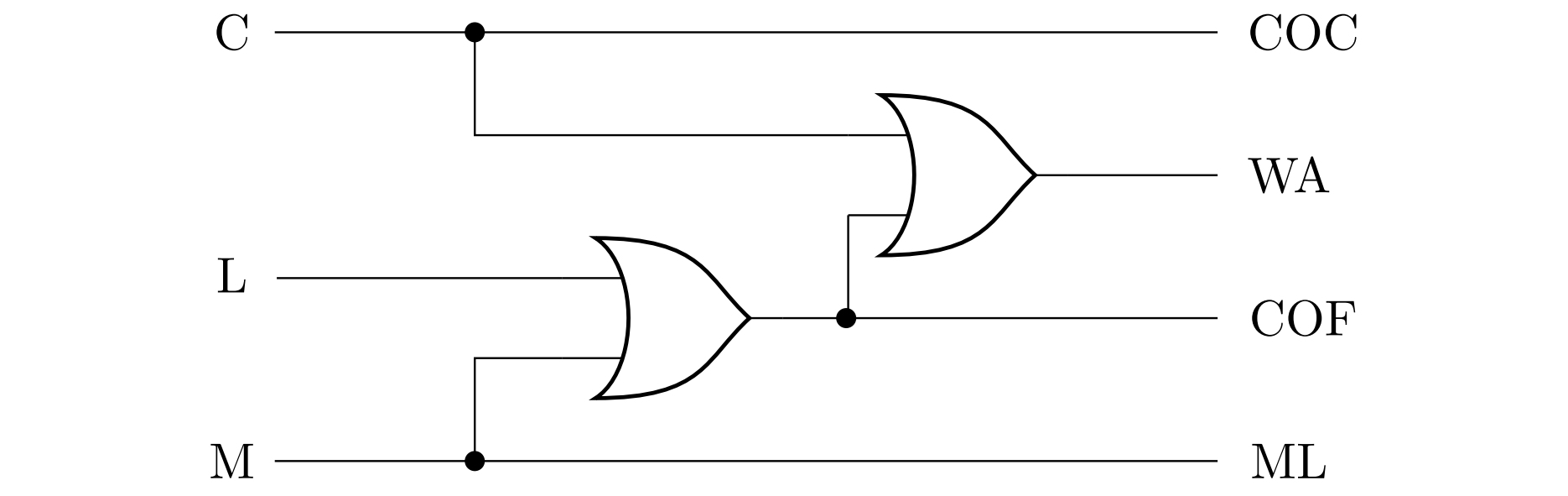
Zadanie 6. Po naciśnięciu odpowiedniego przycisku ekspres może przygotować trzy rodzaje napojów: lungo, macchiato i kakao. Napoje przygotowywane są poprzez zmieszanie czterech składników (gorącej wody, mleka, kawy i koncentratu kakaowego). Każdy składnik ma własną dyszę. Zaprojektuj obwód logiczny z trzema wejściami (po jednym dla każdego napoju) i czterema wyjściami (po jednym dla każdego zaworu dyszy), biorąc pod uwagę, że lungo jest przygotowywane z wody i koncentratu kawy, macchiato z wody, mleka i koncentratu kawy, a kakao z wody i koncentratu kakao.
Dla uproszczenia załóżmy, że nikt nie myśli o naciskaniu wielu przycisków w tym samym czasie, więc nie trzeba zajmować się takimi przypadkami. Składnik jest uwalniany do kubka dokładnie wtedy, gdy na odpowiednim wyjściu pojawi się logiczna jedynka.
Rozwiązanie. Oznaczmy przez \(\mathrm{C}\) (kakao), \(\mathrm{L}\) (lungo) i \(\mathrm{M}\) (macchiato) instrukcje reprezentujące stan naciśnięcia odpowiedniego przycisku, a następnie oznaczmy \(\mathrm{COC}\) (koncentrat kakaowy), \(\mathrm{WA}\) (woda), \(\mathrm{COF}\) (koncentrat kawy) i \(\mathrm{ML}\) (mleko) reprezentujące stan otwarcia odpowiedniej dyszy. Na podstawie informacji zawartych w zadaniu utwórzmy tabelę prawdy:
| \(\mathrm{C}\) | \(\mathrm{L}\) | \(\mathrm{M}\) | \(\mathrm{COC}\) | \(\mathrm{WA}\) | \(\mathrm{COF}\) | \(\mathrm{ML}\) |
|---|---|---|---|---|---|---|
| \(1\) | \(0\) | \(0\) | \(1\) | \(1\) | \(0\) | \(0\) |
| \(0\) | \(1\) | \(0\) | \(0\) | \(1\) | \(1\) | \(0\) |
| \(0\) | \(0\) | \(1\) | \(0\) | \(1\) | \(1\) | \(1\) |
| \(0\) | \(0\) | \(0\) | \(0\) | \(0\) | \(0\) | \(0\) |
Wiersze z więcej niż jedną cyfrą 1 w pierwszych trzech kolumnach nie są brane pod uwagę, ponieważ tylko jeden przycisk może być naciśnięty w danym momencie.
Tabela pokazuje, że równoważną parą stwierdzeń są \(\mathrm{COC}\) i \(\mathrm{C}\). i \(\mathrm{C}\), a inną równoważną parą są stwierdzenia \(\mathrm{ML}\) i \(\mathrm{M}\). Stwierdzenie \(\mathrm{COF}\) jest prawdziwe wtedy i tylko wtedy, gdy jedno ze stwierdzeń \(\mathrm{L}\) lub \(\mathrm{M}\) jest prawdziwe, tj. jest równoważne dysjunkcji \(\mathrm{L}\vee\mathrm {M}\). Wreszcie, stwierdzenie \(\mathrm{WA}\) jest prawdziwe wtedy i tylko wtedy, gdy którekolwiek z trzech stwierdzeń \(\mathrm{C}\), \(\mathrm{L}\), \(\mathrm{M}\) jest prawdziwe, to znaczy \(\mathrm{WA}\) jest równoważne dysjunkcji \(\mathrm{C}\vee\mathrm{L}\vee\mathrm{M}\).
Poniższy rysunek przedstawia schemat odpowiedniego obwodu - dysjunkcja \(\mathrm{C}\vee\mathrm{L}\vee\mathrm{M}\) jest realizowane przez wstawienie dwóch wyrażeń OR, tj. jako \(\mathrm{C}\vee\left( \mathrm{L}\vee\mathrm{M}\right)\).
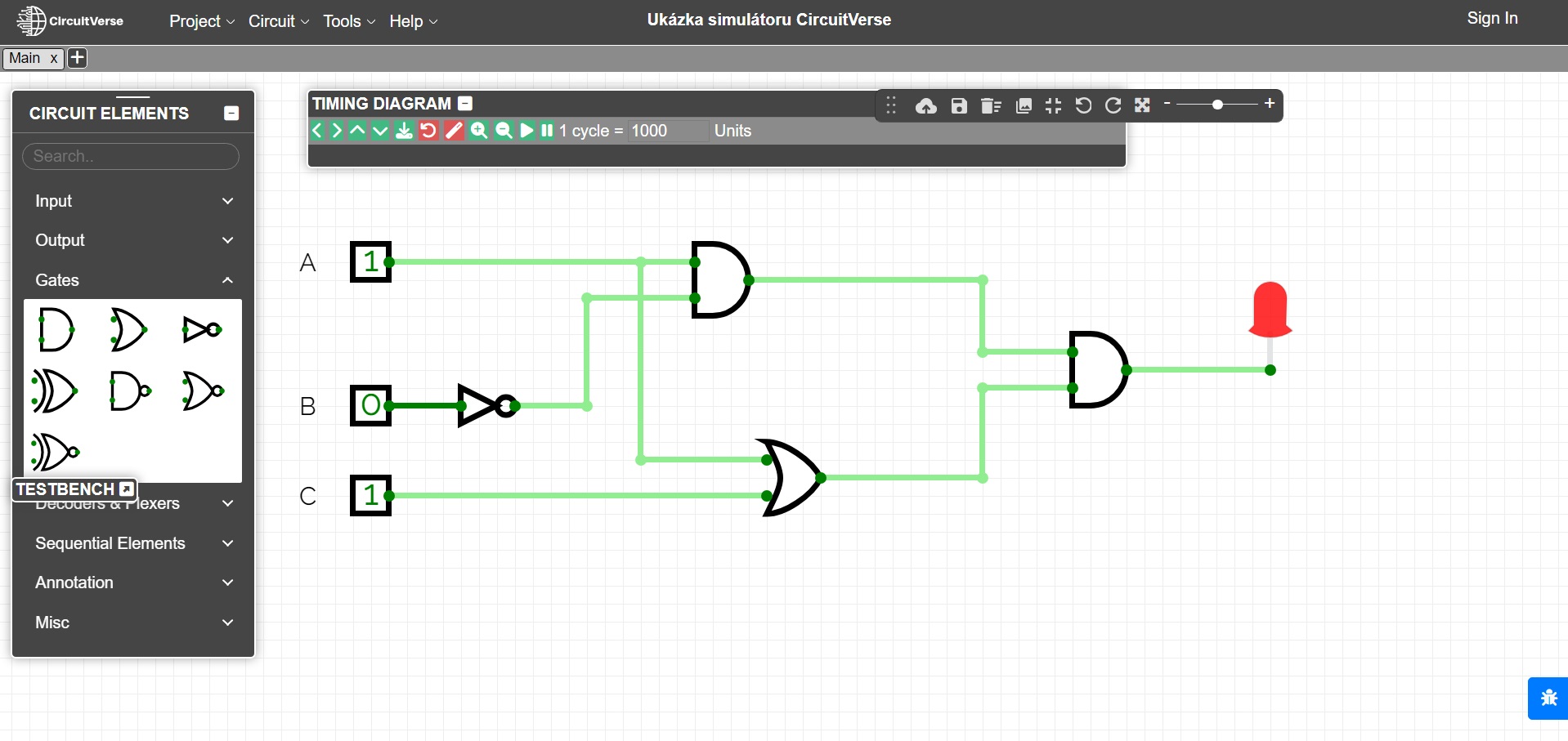
Wszystkie wspomniane ćwiczenia można zilustrować na różnych symulatorach obwodów logicznych, np. symulatorze online CircuitVerse. Na ostatnim rysunku obwód z ćwiczenia 2 jest modelowany za pomocą tego symulatora. Możliwe jest również użycie specjalistycznych zestawów elektronicznych do ilustracji.
Literatura
- Perrin J. P., Denouette M., Daclin E. Logické systémy, díl I. Kombinační logické obvody. Úvod do sekvenčních obvodů. Praha: SNTL. 1972
- Online simulátor CircuitVerse, https://circuitverse.org/simulator
