diff --git a/00031_Glue_Joints/en_article_proofreading.md b/00031_Glue_Joints/en_article_proofreading.md
index fef30d4..dedde49 100644
--- a/00031_Glue_Joints/en_article_proofreading.md
+++ b/00031_Glue_Joints/en_article_proofreading.md
@@ -1,226 +1,225 @@
---
keywords:
-- goniometric functions
+- trigonometric functions
- right triangle
-is_finished: True
+is_finished: False
---
# Glued Joints
-In this arcticle we will show what practical uses can be made of goniometric
-functions and relationships between the lengths of the sides of a right triangle.
+In this article, we demonstrate practical uses of trigonometric
+functions and the relationships between the lengths of the sides in a right triangle.
-We will look at the problem of glued joints. We will show methods of how to
-to distribute the stresses of the joint into distinct components and over a larger area, and
-how to determine the stresses in such a joint. We will calculate stresses on a diagonal joint in a bar, if the bar is loaded by an axial force, as shown in the figure.
+We focus on the topic of glued joints – connections made using adhesive materials.
+We show how to break down the force acting in a joint into components, distribute it across a larger area, and determine the resulting stress in the joint. We will calculate how stress changes in a slanted joint of a bar, if the bar is loaded by an axial force, compared to a perpendicular joint, as ilustrated in the figure.

-## Types of glued joints and their loading
+## Types of Glued Joints and Their Stress
-Everyone is familiar with joining of materials by gluing. If the strength
-of the resulting joint doesn't matter, bonding is one of the easiest ways
-of joining materials. In practice, however, we often need the joint to be
-durable and strong. This means, the joint should not fail when loaded by forces.
+Everyone is familiar with joining materials by gluing. When the strength
+of the resulting connection is not critical, gluing is one of the simplest ways
+to join materials. In practice, however, we often need the joint to be both
+durable and strong. This means the joint should not fail when subjected to significant loading by forces. In engineering, glued joints are also referred to as bonded joints.
-Adhesives usually guarantee resistance to normal tensile stresses and
-to shear stresses that do not exceed the values specified by the manufacturer
-of the adhesive. By stress we mean the mechanical stress which is a quotient of
-of the applied force and the area on which the force is applied. In the case of
-normal stress, the force perpendicular to the surface is considered, in the case of stress
-shear, the force is parallel to the surface. The deformation caused by these forces
-are shown on the left, with "Tensile" illustrating normal tensile stress and "Shear" illustrating shear stress.
+Adhesives (glues) typically guarantee resistance to normal stress (tensile forces) and shear stress (sliding forces), as long as stresses do not exceed the values specified by the adhesive’s manufacturer.
-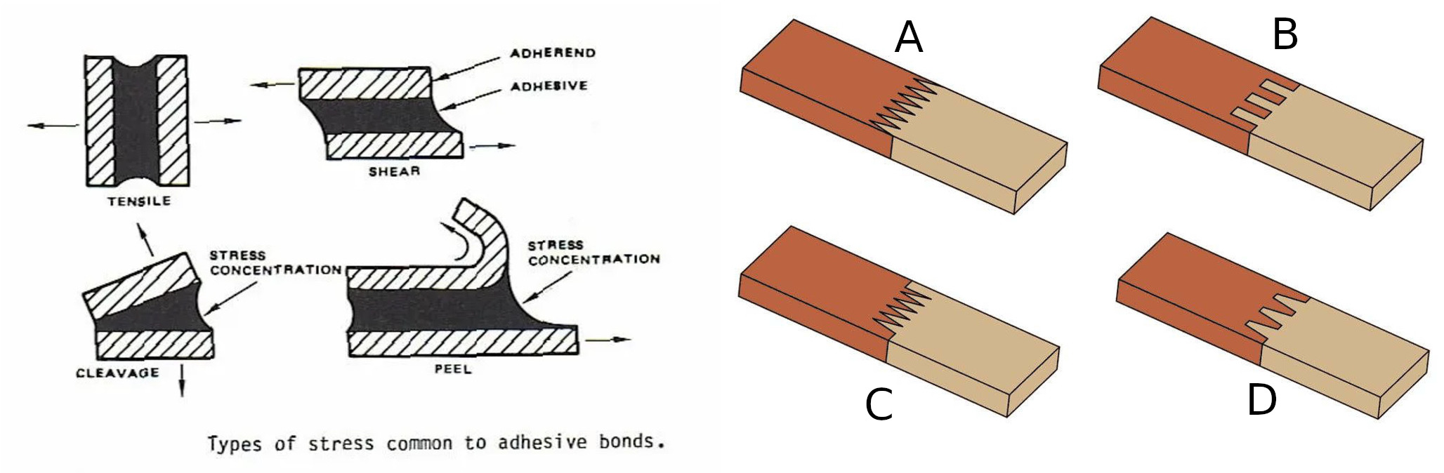
+Stress refers to mechanical pressure, defined as the ratio of the applied force to the area over which the force acts.
+In the case of
+normal stress, the force acts perpendicular to the surface. In the case of shear stress, the force acts parallel to the joint surface. The deformations caused by these forces
+are shown on the left: "Tensile" illustrates normal stress from perpendicular force, while "Shear" illustrates shear stress from parallel force.
-The strength of the joint is related to the adhesive used and the materials bonded. Data can be found from manufacturers and may look as follows:
+
-* A joint bonded with Loctite 421 instant adhesive has a strength of 18MPa to 26
- MPa on steel and 5MPa to 20MPa on polycarbonate.
-* A joint bonded with Herkules dispersion adhesive has a shear strength of
- bonding of wood 8MPa.
-* A joint bonded with MAMUT Glue has a tensile strength of 2.18MPa and a shear strength of 1.40MPa.
-Since the stress of a joint is determined as a ratio of force to area, to reduce
-stresses, we try to reduce the force by spreading the force in more directions and
-over a larger area. An example is the joint in the previous figure on the right. For the joint
-B, the faces subjected to normal stress are supplemented with faces
-loaded by pure shear.
+The strength of a joint depends on the adhesive used and the materials being joined. Manufacturer data may look as follows:
-For us, the slanted joint will be more interesting, because
-the joint is subjected to both normal and shear
-stresses. It should be noted that in practice we often see an oblique connection implemented
-in a different way thank shown in the Figure 1. The reason is that it is preferable to have the joint
-more slanted, but a too slanted joint would take up too much space. In practice
-such a joint is therefore implemented with interruptions, with a rotation of every second
-and with each part aligned on top of the other.
+* A joint glued with Loctite 421 (a superglue) has a strength of 18 MPa to 26 MPa on steel and 5 MPa to 20 MPa on polycarbonate.
+* A wooden joint glued with Herkules (a dispersion adhesive) can withstand 8 MPa of shear stress.
+* A joint glued with MAMUT Glue has tensile strength of 2.18 MPa and shear strength of 1.40 MPa.
-
+Since stress in a joint is calculated as the ratio of the force to the area, one effective way to reduce
+stresses is to decompose the force into multiple directions and spread it
+over a larger area.
+On the right side of the previous picture, examples are shown. In joint B, the front faces are subjected to normal stress, while additional faces are loaded by pure shear stress.
+We will pay special attention to slanted joints, where the connection is subjected to both normal and shear stresses simultaneously.
+In practice, slanted joints are often implemented differently than in Figure 1. A greater slant increases the joint strength but also takes up more space. That's why slanted joints are usually built with interruptions, rotated layers, and stacked alignment of glued segments.
-## Stresses on the slanted joint
+
+
+
+## Stress in a Slanted Joint
> **Task 1.**
-> Consider a bar with width $b=4\mathrm{cm}$ and height $h=3\
-> $mathrm{cm}$, which is glued together from two pieces by an angled joint according to
-> figure.
+> Consider a bar with height $h=3\mathrm{cm}$ and width $b=4\mathrm{cm}$, glued together from two pieces along a slanted joint as shown in the figure.
+> The angle between the joint plane and the plane of a cross-section perpendicular to the axis of the bar is $\alpha=30^\circ$. The bar
+> is subjected to an axial force $F=1\ 000\ \mathrm{N}$.
+> Calculate the normal and shear stresses in the slanted joint and compare them with the normal stress in the cross-section perpendicular to the axis.
+>
> 
-> The angle between the joint and vertical direction is $\alpha=30^{circ}$. The bar
-> is loaded axially by a force $F=1^,000^mathrm{N}$.
-> Calculate the normal and shear stresses on the joint and compare with the normal stress in a plane perpendicular to the axis.
\iffalse
*Solution.*
-In a plane perpendicular to the axis, the cross section is a rectangle with sides $b$ and $h$.
-The corresponding normal stress is
-$$
-\sigma = \frac{F}{bh}
-= \frac{1000\,\mathrm{N}}{3\times 4 \mathrm {cm}^2} = 833\,333\\mathrm{Pa} = 0{,}833\, \mathrm{MPa}.
-$$
+In a plane perpendicular to the axis, the cross-section is a rectangle with sides $b$ and $h$.
+The axial force $F$ causes only normal stress in this section:
+
+$$\sigma = \frac{F}{bh}
+= \frac{1\ 000\ \mathrm{N}}{(3\times 4) \ \mathrm {cm}^2} = 833\ 333\ \mathrm{Pa} = 0.833\ \mathrm{MPa}.$$
+
+The normal stress in the slanted joint, $\sigma_N$, is given by:
+
+$$\sigma_N = \frac{F_N}{A},$$
-The normal stress $\sigma_N$ is calculated by
-$$\sigma_N = \frac{F_N}{S},$$
-where $F_N$ is the magnitude of the normal force and $S$ is the surface area
-of the joint. The shear stress $\sigma_G$ is calculated similarly to the normal stress
-by the relation
-$$\sigma_G = \frac{F_G}{S},$$
-where $F_G$ is the magnitude of the shear force.
+where $F_N$ is the component of the force normal to the joint and $A$ is the area
+of the joint. Similarly, the shear stress in the slanted joint, $\sigma_S$, is given by:
-In a right triangle with hypotenuse $F$ and sides $F_N$ and $F_G$, we can determine the interior angles due and from this triangle we obtain the magnitudes of the forces $F_N$ and $F_G$:
+$$\sigma_S = \frac{F_S}{A},$$
+
+where $F_S$ is the component of the force parallel to the joint.
+
+The axial force $F$ is decomposed into components of normal force, $F_N$, and shear force, $F_S$. These components form sides of the right triangle with hypotenuse $F$ and with the given angle $\alpha$ between one of the sides and hypotenuse (see the picture). From relationships between parameters of this triangle we calculate the magnitudes of the forces $F_N$ and $F_S$:
$$
-\³{aligned}
-F_N&=F\cos \alpha\
-F_G&=F\sin \alpha
+\begin{aligned}
+F_N&=F\cos \alpha,\\
+F_S&=F\sin \alpha.
\end{aligned}
$$
-
+
-The joint will have the shape of a rectangle. One side of the joint will be equal to the width
-of the bar. The length $c$ of the other side is the length of the hypotenuse of the right
-triangle with the hypotenuse $h$ and the interior angle
+The shape of the joint surface is a rectangle. One side of this rectangle equals to the width
+of the bar, $b$, and the other side, $c$, is the hypotenuse of a right
+triangle with side $h$ and the adjacent interior angle
$\alpha$.
-Thus
-$$
-c=\frac{h}{\cos \alpha}
-$$
-a
-$$A=bc=\frac{hb}{\cos\alpha}.$$
+Thus, we calculate the length of $c$ as:
-Using these computations we get the normal stress
-$$
-\sigma_N = \frac{F_N}{A} = \frac{F\cos\alpha}{\frac{hb}{\cos \alpha}} =
-\frac{F}{hb}\cos^2\alpha = \sigma\cos^2\alpha
-$$
-and the shear stress
-$$
-\sigma_G = \frac{F_G}{A} = \frac{F\sin\alpha}{\frac{hb}{\cos \alpha}} =
-\frac{F}{hb}\sin\alpha\cos\alpha = \sigma\sin\alpha\cos\alpha.
-$$
+$$c=\frac{h}{\cos\alpha},$$
-The values of the goniometric functions $\sin\alpha$ and $\cos \alpha$ reveal the shear and normal stress in the joint as a fraction of the normal stress in the plane perpendicular to the axis. Since both these factors are less than one, both stresses $\sigma_N$
-and $\sigma_G$ are less than $\sigma$. The functions $\sin x\cos x$ and
-$\cos^2x$ are shown in the figure below. For the angle $\alpha=30^\circ$ and the given
-bar dimensions and force parameters we get
-$$
-\sigma_N=0{,}625\,\mathrm{MPa}
-$$
-a
-$$
-\sigma_G=0{,}361\,\mathrm{MPa}.
-$$
+and the area of the joint is:
+
+$$A=bc=\frac{bh}{\cos\alpha}.$$
+
+Using the above computations, we obtain for the normal stress:
+
+$$ \sigma_N = \frac{F_N}{A} = \frac{F\cos\alpha}{\frac{bh}{\cos \alpha}} = \frac{F}{bh}\cos^2\alpha = \sigma\cos^2\alpha,$$
+
+and for the shear stress:
+
+$$\sigma_S = \frac{F_S}{A} = \frac{F\sin\alpha}{\frac{bh}{\cos \alpha}} =
+\frac{F}{bh}\sin\alpha\cos\alpha = \sigma\sin\alpha\cos\alpha.$$
+
+
+The values of the trigonometric functions, $\sin\alpha$ and $\cos\alpha$, determine in what ratio the stress in the joint is divided into normal and shear components. Since both these factors are less than one, both stresses, $\sigma_N$
+and $\sigma_S$, are less than $\sigma$, which is the stress in the cross-section perpendicular to the bar axis.
+The graphs of the functions $\sin x\cos x$ and
+$\cos^2x$ are shown in the figure below. For the angle $\alpha=30^\circ$, and the given
+bar dimensions and axial force magnitude, we get:
+
+$$\sigma_N=0.625\ \mathrm{MPa},$$
+
+and
+
+$$\sigma_S=0.361\ \mathrm{MPa}.$$
\fi
-
+
## Supplementary exercises
-> **Problem 2.** Determine the angle for which the shear stress in
-> Problem 1 is maximal. Also determine the corresponding normal stress.
+> **Problem 2.** Determine the angle of the slanted joint (as described in
+> Problem 1) for which the shear stress is maximal. Also determine the corresponding normal stress.
\iffalse
*Solution.*
-In Problem 1, the formula for the shear stress was derived in the form
+In Problem 1, the formula for the shear stress was derived in the form:
-$$
-\sigma_G=\sigma\sin\alpha\cos\alpha.
-$$
+$$\sigma_S=\sigma\sin\alpha\cos\alpha.$$
-Applying the formula for double the angle gives
+Using the trigonometric identity, $\sin 2\alpha=2\sin\alpha\cos\alpha$, we obtain:
-$$
-\sigma_G=\frac 12\sigma\sin(2\alpha)
-$$
+$$\sigma_S=\frac 12\sigma\sin(2\alpha).$$
+
+This expression reaches its maximum when $\sin(2\alpha) = 1$ that is at $\alpha = 45^\circ$ (see also the figure in the solution of Problem 1).
+In that case, we have:
-and from here we see (see also the figure in the solution of Problem 1) that the maximal value of the shear stress is for the angle $\alpha=45^\circ$ and in this case $\sigma_G=\frac 12\sigma$ holds.
+$$\sigma_S=\frac 12\sigma.$$
+
-For the normal stress we derived the formula
+For the normal stress, the derived formula is:
-$$\sigma_N=\sigma\cos^2\alpha$$
+$$\sigma_N=\sigma\cos^2\alpha.$$
-and for $\alpha=45^\circ$ we get $\sigma_N=\frac 12\sigma.$ At maximum shear stress, both shear and normal stresses will be equal and equal to half the value of $\sigma$. This situation occurs for a joint at an angle of $45^\circ$.
+For $\alpha=45^\circ$, we get:
+
+$$\sigma_N=\frac 12\sigma.$$
+
+At maximum shear stress, both the shear and normal stresses are equal and each is half the value of $\sigma$. This situation occurs when the joint is slanted at an angle of $45^\circ$.
\fi
-> **Problem 3.** The adhesive guarantees that the joint will resist normal stress
-> $10^mathrm{MPa}$ and shear stress of $8^mathrm{MPa}$. What
-> maximum force can be applied to the joint in Problem 1? How would the answer to
-> this question change for a joint at an angle of $45^{\circ}$?
+> **Problem 3.** The adhesive guarantees that the joint can withstand a normal stress of
+> $10\ \mathrm{MPa}$ and shear stress of $8\ \mathrm{MPa}$. What is then the
+> maximum force that can be applied to the slanted joint described in Problem 1? How would the answer to
+> this question change if the joint was slanted at an angle of $45^{\circ}$?
\iffalse
*Solution.*
-We isolate $\sigma$ from the derived relations for both stresses. We obtain
+We express $\sigma$ using the previously derived formulas for both stress components:
$$\sigma=\frac{\sigma_N}{\cos^2\alpha}$$
and
-$$\sigma=\frac{\sigma_G}{\sin\alpha\cos\alpha}.$$
+$$\sigma=\frac{\sigma_S}{\sin\alpha\cos\alpha}.$$
+
+Further we express the stress $\sigma$ using the relation:
-Further we evaluate the stress $\sigma$ using the force $F$ by the formula $$\sigma=\frac{F}{bh}.$$ Substituting this formula in the above relations and isolating the force $F$ we get
+$$\sigma=\frac{F}{bh}$$
-$$F=\frac{bh\sigma_N}{\cos^2\alpha}$$
+with the axial force $F$. Substituting this expression for $\sigma$ into the equations above and solving for $F$, we obtain:
+
+$$F=\frac{bh\ \sigma_N}{\cos^2\alpha}$$
and
-$$F=\frac{bh\sigma_G}{\sin\alpha \cos\alpha}.$$
+$$F=\frac{bh\ \sigma_S}{\sin\alpha \cos\alpha}.$$
-For the dimensions from Problem 1 and for the given $\sigma_N=10\,\mathrm{MPa}$ and $\sigma_G=8\,\mathrm{MPa}$ we have
+Using the dimensions from Problem 1 and the given maximum stress values, $\sigma_N=10\ \mathrm{MPa}$ and $\sigma_S=8\ \mathrm{MPa}$, we find that the axial force must not exceed:
-$$F=\frac{3\times 4\,\mathrm{cm}^2 \times 10\,\mathrm{MPa}}{\cos^2 30^\circ}=16\,000\,\mathrm{N}$$
+$$F=\frac{(3\times 4)\ \mathrm{cm}^2 \times 10\ \mathrm{MPa}}{\cos^2 30^\circ}=16\ 000\ \mathrm{N},$$
-and
+or
-$$F=\frac{3\times 4\,\mathrm{cm}^2 \times 8\,\mathrm{MPa}}{\sin 30^\circ\cos 30^\circ}=22\,170\,\mathrm{N}.$$
+$$F=\frac{(3\times 4)\ \mathrm{cm}^2 \times 8\ \mathrm{MPa}}{\sin 30^\circ\cos 30^\circ}=22\ 170\ \mathrm{N}.$$
-Therefore, the maximum force that can be applied to this joint is $16,000\,\mathrm{N}$.
+Therefore, the maximum force that can be applied to this joint is $16\ 000\ \mathrm{N}$, limited by the normal stress criterion.
-Similarly, for an angle $\alpha = 45^\circ$, we get the values
+Similarly, for an angle of $\alpha = 45^\circ$, which corresponds to the maximum sheer stress in the joint, we obtain the following force values:
-$$F=\frac{3\times 4\,\mathrm{cm}^2 \times 10\,\mathrm{MPa}}{\cos^2 45^\circ}=24\,000\,\mathrm{N}$$
+$$F=\frac{(3\times 4)\ \mathrm{cm}^2 \times 10\ \mathrm{MPa}}{\cos^2 45^\circ}=24\ 000\ \mathrm{N}$$
-and
+or
-$$F=\frac{3\times 4\,\mathrm{cm}^2 \times 8\,\mathrm{MPa}}{\sin 45^\circ\cos 45^\circ}=19\,200\,\mathrm{N}.$$
+$$F=\frac{(3\times 4)\ \mathrm{cm}^2 \times 8\ \mathrm{MPa}}{\sin 45^\circ\cos 45^\circ}=19\ 200\ \mathrm{N}.$$
-From here we see that the maximum force that can load the joint in this case is $19\,200\,\mathrm{N}.$
+Therefore, the maximum force that can be applied to the joint is $19\ 200\ \mathrm{N}$. This value is higher than for $\alpha = 30^\circ$ indicating that a slant angle of $\alpha = 45^\circ$ allows a greater applied force due to the optimal distribution of stresses.
\fi
-
## Concluding remarks
### Stresses in the plane of the connection
We have studied the forces that try to break the joint by normal
-stresses perpendicular to the joint and shear stresses. In addition, the force
+stresses acting perpendicularly to the joint and shear stresses acting in the plane of the joint. In addition, the force
action can still stretch the joint as a whole in the plane of the joint. In
the above analysis, we were not interested in this component. However, it
can be obtained from the formula for the normal stress $\sigma_N$ by rotating by 90 degrees.
@@ -228,22 +227,21 @@ can be obtained from the formula for the normal stress $\sigma_N$ by rotating by
### Defect analysis
Stress decomposition into pre-selected directions is also used in other
-engineering practice situations than bonding. For example, if there is an internal defect in a stressed material, knowledge of the streses in various planes will allow
+engineering practice situations than bonding. For example, if there is an internal defect in a stressed material, knowledge of the stresses in various planes will allow
to assess the risk of further propagation of this defect. In this case it is natural
to transform the mechanical stresses into the direction of the defect in the same way that we
transformed into the direction of the joint.
-
### Mechanical modelling of composite materials
-It is appropriate to transform the mechanical stresses into the predefiend directions even when
-studying the deformation of composite materials. This includes both artificial
+It is appropriate to transform the mechanical stresses into the predefined directions even when
+studying the deformation of composite materials. This includes both artificial
composites or natural composites. Artificial composites include
-fibre-reinforced materials. Natural composites include
-the most widely used structural material, wood. These composites have different properties in different directions and when studying behavior of these materials under machanical load it is easier to study
-to study separately the stresses in the directions related to the structure of this
-composite. For example, the stresses in the direction of the stiffening fibres in artificial
-composites, or stresses in the longitudinal direction for wood. In general, we study the stresses in the axes or planes of symmetry of the material and in directions perpendicular to these planes, the so called princpal directions. The response of the material to loads in the principal directions is known. The response to
+fiber-reinforced materials. Natural composites include
+the most widely used structural material, wood. These composites have different properties in different directions and when studying behavior of these materials under mechanical load it is easier to study
+ separately the stresses in the directions related to the structure of this
+composite. For example, the stresses in the direction of the stiffening fibers in artificial
+composites, or stresses in the longitudinal direction for wood. In general, we study the stresses in the axes or planes of symmetry of the material and in directions perpendicular to these planes, in the, so called, principal directions. The response of the material to loads in the principal directions is known. The response to
loads in other directions can be determined by decomposing the stresses into
the individual principal directions, determine the corresponding deformations and transform this information back to obtain the final material response. Engineers know this technique as the so-called tensor transformation and have a number of
techniques to solve problems of this type quickly and efficiently.
@@ -256,9 +254,10 @@ techniques to solve problems of this type quickly and efficiently.
* <https://www.druchema.cz/z1530-herkules-250g>, online, 2024-04-28
* <https://www.deko.ee/en/a/mamut-glue-25ml-25-ml>, online, 2024-04-29
-
### Image sources
* https://theepoxyexperts.com/general-bonding-design-guideline/
* https://homemade-furniture.com/woodworking-joints/finger-joint/
* https://commons.wikimedia.org/wiki/File:Glue_Bottle_-_The_Noun_Project.svg
+
+